����������
Hydrogen rectifier
ʹ �� ˵ �� ��
1 . ����
1.1 KGHSϵ�пɿع����Դ�Dz���ˮ��ʽ��բ�ܵ�ѹ��ֱ������
�豸����������ˮ���������ҵ�������绯ѧ����ҵ��
1.2�ͺź���
KG H S
������ѹ��V��
 ����������A�� ����������A�� ��ȴ��ʽΪˮ�� ��ȴ��ʽΪˮ��  �����; �����; ��բ�� ��բ��2 . ʹ������
��Ʒ����������������ʹ��
2.1 ���θ߶Ȳ�����1000�ף�
2.2 ��Χ�����¶Ȳ����ڣ�40�棬������+5�棻
2.3 ����������ʪ�Ȳ�����90%��20��5��ʱ����
2.4ʹ�ó�������ȼ�ױ�ըΣ�գ������Ը�ʴ�������ƻ���Ե�ĵ��糾��
�����壻
2.5�����ͳ������ֱ��б�Ȳ�����5��ij�����
2.6�ڵ�����ѹ������5%�������������ѹ��
2.7��ȴˮ�����¶Ȳ�����+5��C��������+35��C��
2.8ˮ��Ӧ����:
2.8.1�����ʲ�С��10��103��cm.
2.8.2PHֵ��6-9֮��.
2.8.3����ȴˮ������������ʱ,����������ΪGB3859-83��4.1.2.4����֮�涨.
2.8.4��ˮ�ڱ���ӹ�������
3 . ��Ҫ��������������
3.1�����淶
|
�� �� �� �� |
�� �� |
�� �� |
|
�ߵ�ѹ��V�� |
�ߵ�����A�� |
��ѹ��V�� |
������A�� |
|
KGHS��1050A/72V |
380 |
146 |
72 |
1050 |
|
|
|
|
|
|
3.2�����ԴΪ���������ƣ�������ѹ380V��5%��Ƶ��Ϊ50Hz��
3.3ֱ�������ѹ�������ڶ��Χ��0-100%�����ɵ������صȼ���
3.4�����ֶ�ת������������ѹ�������й��ܣ��������ȡ�1.0%, ��ѹ���ȡ�1.5%��
3.5����Զ��������������ֹͣ���ܡ�
3.6�������ڲ��任�������ڵ�ѹΪ0-75V/4-20mA�����ڵ���Ϊ0-1500A/4-20mA�����һ��������������������ѹ����������4-20mA�����źŸ��ⲿ��PLC������PLC�����4-20mA�����źſɽ����Զ��������������
3.7��������·�Ĺ��������۶ϡ�ȱ�ࡢȱˮ����բ�ܳ��¡���ͣ���й������ⱨ�����ж�����·�ȱ������ܡ�
3.8���������ȼ�B����
3.9������ֱ�����Ϊ����������������
4 . �ṹ�ص㼰���γߴ�
4.1�������GGD���ͣ������ѹ�����а�װʹ�ã���Ƿ����ȼ� IP-20(GB4208-84)
4.2����װ�������ž�բ��������·����ˮ��ɢ��������բ�ܴ�����������
���ۣ��۶����������Ӵ������̵����ȵ�������Ԫ������װ����ˮ�����ƣ���ӵ�ѹ����.
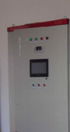
4.3�����װ�������ѹ��������ָʾ�DZ��Լ�ָʾ�ơ����ƿ��ء�����
��ť�͵�����ť�ȡ�
4.4���������ڹ���ǰ���²���ֱ������ڹ����������²࣬����ǰ���ţ�����ά������ޡ�
4.5���γߴ�
|
�� �� �� �� |
�� �� �� �磨mm�� |
|
����B�� |
�D�� |
�ߣ�H�� |
|
KGHS��1050A/72V |
1000 |
800 |
1850 |
|
|
|
|
|
5 . ����ԭ��
5.1����ԭ��ͼ������ͼ��
5.2ԭ������ͼ
���ཻ������ ֱ�����
  5.3����ԭ�� 5.3����ԭ��5.3.1 ���ཻ���羭�����۶�����1-3FU���ͽӴ�����0KM������������
ѹ��һ�β࣬��ѹ����1-3FF�������ţ�1-6VT�����ɿɵ���ֱ��
�������
5.3.2 1-6VT��բ�ܵĴ����źż�������ɾ�բ�ܱջ�����������AP�ṩ��AP��һ�������ģ�����ִ����������п����ͱջ����ֿ���ʽ����ѹ������������ѹ���ֵ��ڷ�ʽ�Լ�������ѹ�������ܡ�������������Ӧ���ϵ�����������ܡ�������Ƶ�ѹΪ0��-10V������������AP
����������С���Դ������ʧ�ء�����������������ѹ���������������ָʾ��
����������ܣ�����ʾ������ �Ĺ���״̬����������Դ����ʱ����Դ�������������·�쳣ʱ��ʧ�ء��������������ѹʱ�������������ĸ�·������������ʱ����Ӧ�ĵ�����
5.3.3 ���������й��������۶ϡ�ȱ�ࡢȱˮ����բ�ܳ��¡���ͣ�źű���װ�ã������У�������ijһ�ֹ��ϳ���ʱ������Ӧָʾ������
���ж�����·�������ⱨ����ͬʱ���ⲿһ�����ϸɽӵ��źš�
5.3.4 ������·�ɽ����Ӵ�����0KM�������м�̵�������ֹͣ����λ�Ȱ�ť��1-6SB���Լ���·�̵�����1-9KA�������ڵ�λ����RP������ɡ�
6 . ��װ���Լ�ʹ��
6.1��װ
6.1.1���豸Ӧ��װ��ͨ����û�и�ʴ������Զ����Դ�ij�����
6.1.2����Ӧ����ľ���߶�Ϊ80-100mm������ʹ��������ʱ�����õ�
ͨ�磬��ʪ����Ӧ��ȡ������ʩ������ʹ����Ԫ���ܳ��ƻ��������Ե�̶ȡ�
6.1.3�豸Ӧ�����õĵ��ߡ�
6.1.4�豸��װ���,��ˮ·��ͨ����ˮ������ˮѹ���ø���2Kg/cm2�������ܵ���1Kg/cm2����ͬʱ��������ˮ,©ˮ�ĵط�.
6.2������ʹ��
6.2.1ʹ��ǰ�����Ķ�˵���飬���������̼����Ӳ�������ߵȣ�ȷ��
��ȷ����
6.2.2�����ཻ����Դ�������A��B��C��N��������ϣ����뱣���ӵ���PE��ͬʱֱ������˽����ʵ����ء�Ȼ���ͨˮԴ��
6.2.3������ϵġ����ء�����ء�ת������1SA���ڡ����ء�λ�ã�������ϡ�������ڡ�ť��ʱ������㣬�����û���������ѡ�����������ѹ��ת������2SA���ڡ���ѹ�������������ѹ��ڴ�����AP���ڡ��ջ��������ϵ�Դ����ʱ��������Դ��������
6.2.4������������ť��������������·ǰӦ�ȸ����ⲿ�����źţ��������������5��6�պϣ�ͬʱ���ⲿ�����źţ��������������9��10�Ͽ������Զ�̸�λ���ܹ��ܲ��õĻ�������һ���Ѷ����������21��22�̽ᡣ�������С�ָʾ������˳ʱ����ڡ�������ڡ���λ������ʱ��ѹ������ֵ����������ֱ���ฺ�ص�����ʣ������ֵ��
6.2.5���豸����ʱ�������������1.05����������������������������ָʾ������ͬʱ�ж�����·���������ⱨ����ͬʱ���ⲿһ���ɽӵ��źţ���������λ����ť�ɽ������������������״̬�����豸���ڡ���ء�ʱ���豸���غ�Ӧ������λ������ʹ�豸��λ�������ٴ����豸����������������ť��ɽ�����屨�������Dz��ܽ��������������״̬�������豸�����ٴ�����ˮѹ����ʱ��ˮѹ������������Ƿˮѹ��ָʾ������ͬʱ�ж�����·���������ⱨ����ͬʱ���ⲿһ���ɽӵ��źţ���ˮѹ�ָ�����ʱ����������λ����ť�ɽ��������Ƿˮѹ��������״̬��
6.2.6�ֱ����ÿ��۶ϡ�ȱ�ࡢȱˮ����բ�ܳ��¡���ͣ�������ϣ���ʱ��Ӧָʾ���������ж�����·�������ⱨ����ͬʱ���ⲿһ���ɽӵ��źš��������ֱ���ֻ���ų����ϲ��ܽ��ָʾ���ٴ����豸�����ɰ�����������ť������屨����
6.2.7�û��ɸ��ݹ���������ֱ�ѡ������������ѹ��״̬����ʱӦ�Ѵ�����AP������ڡ��ջ���״̬���û���ʹ���豸ʱ������������������ϵ��趨���ڴ������ϡ����������ջ���ת���������ڿ���ʱ���������豸�����ڡ�������״̬��
6.2.8�����ⲿ���Ƶ���������ɽ������ء�����ء�1SA���ڡ���ء�λ�ü��ɣ���ʱ���������ֹͣ���ⲿ�Ŀ��������ƣ��������������ⲿ��4-20mA�����źŽ��е��ڡ�����װ��4-20mA/0~-10V�ı任�����ɽ�4-20mA�źű�ɴ�����AP��Ҫ��0~-10V�����źš�������������ͣ���ƺ�������ڲ��������á�
6.2.9 ����1QFΪ�ٸ������ÿ��أ����豸����ʱʹ�ã����豸����ʱ�˿����Խ�ʡ���ܡ�
6.2.10����������ӵ���������߶���ͼZLG-1��24��
7 . ά���뱣��
7.1���豸����������£�ÿ��Ӧά��һ�Σ�����������ڻҳ���ÿ����
����һ�Ρ�
7.1.1���м�ǿѲ�ӣ�ע��ˮѹ��1-2kg֮�䣬���ɳ�ѹ�������ӿڻܣ���Ҫ��֤ˮ������800L/H-1000L/H֮�䡣
7.1.2����������ʹ�������£�һ��������꣬����ʹ��Ҫ��ǿ��ܣ�������Ӧ������
7.1.3ˮ��ͷ����������ʹ��2�꣬����Ӧ���������
7.1.4����ʹ�������£�ÿ��Ҫ����ͷһ�Σ��Է�©ˮ��
7.2 ��բ������ǿ��ˮ��������¹�����,�������豸����ˮ��ȴ����������У�ˮ·�Ĺ��������û��Ա���Ӧ������ϴ��ȷ��ˮ·��ͨ��
7.3����
��Ʒ������ɹ�����꣬Ӧ���ڿ�����ͨ��Χ�����¶Ȳ�����+40�棬
������+5�棬����������ʪ�Ȳ�����90%������ڿ����¶�20��5
��ʱ���Լ���ʴ������Ļ����У������������¶��˪����
7.4����
��Ʒ����������У���Ӧ�о�����ײ���͵��š�
8 . ��Ҫ�������ϸ��
|
Ԫ�����Ʒ��� |
�� �� �� |
�� ��
1-3FF |
��բ��
1-6VT |
|
1-3FU |
4-11FU |
|
Ԫ���ͺŹ�� |
NT1-200A
|
RT18-32 |
RS9-380V/1200A(P) |
KP800A/800V |
|
2A 4A |
9 . ��ͼ
9.1����ԭ��ͼ
9.2�������ZLG����ͼ
|
1 |
2 |
3 |
4 |
5 |
6 |
7 |
8 |
9 |
10 |
11 |
12 |
13 |
14 |
15 |
16 |
17 |
18 |
19 |
20 |
21 |
22 |
|
1 |
2 |
3 |
4 |
5 |
6 |
7 |
8 |
9 |
10 |
11 |
12 |
13 |
14 |
15 |
16 |
17 |
18 |
19 |
20 |
21 |
22 |
1. 2��Ϊ������״̬���������ڲ�һ�Գ����ӵ㣬��������������ʱ�պϡ�
3��4��Ϊ��������ϱ����ź������Ϊһ�Գ����㡣
5��6���������ⲿ���������˽ӵ�պϲ�����ʱ��ͬʱ�ⲿ�����Ͽ�����������Թ������˽ӵ��ʱ������ͣ����ͬʱ�����ָʾ����ʾ�����ô˹���ʱһ����ZLG��5��6���Ӷ̽Ӳ��������豸��
7. 8���������ⲿ��ͣ�źţ����˽ӵ�պϲ�����ʱ�������������˽ӵ��ʱ������ͣ����
9. 10���������ⲿ���������˽ӵ������ʱ��ͬʱ�ⲿ�����պϣ���������Թ������˽ӵ�պ�ʱ������ͣ����ͬʱ���ָʾ����ʾ�����ô˹���ʱһ����ZLG��9��10���ӶϿ����������豸��
11. 12�����ö��ӡ�
13. 14��Ϊ�ⲿ��ͣ�����ӵ㡣
15��16�������������������Ӧ��4-20mA�����ź������15Ϊ����16Ϊ����
17. 18���������������ѹ��Ӧ��4-20mA�����ź������17Ϊ����18Ϊ����
19. 20���������������4-20mA�ź�������ӣ�19Ϊ����20Ϊ����
21��22��Զ�̸�λ���ӣ����ô˹���ʱһ����ZLG��21��22���Ӷ̽Ӳ��������豸����
23��24�����ö��ӡ�
Operation Manual of rectifying cabinet for hydrogen production by Water Electrolysis 1. Overview 1.1kghs series SCR electrolytic power supply is a DC power supply using water-cooled thyristor voltage regulator, which is suitable for hydrogen production by water electrolysis or other electrochemical industries. 1.2 type meaning KG H S rated output voltage (v) rated output current (a) cooling mode for water cooling, electrolytic use, thyristor 2. Conditions of use, the product shall normally be used under the following conditions: 2.1 elevation not exceeding 1000 m; 2.2 ambient temperature not higher than + 40 ��C, not lower than + 5 ��c; 2.3 maximum relative humidity of air not exceeding 90% (at 205 ��c) ; 2.4 there is no inflammable and explosive danger, no conductive dust and gas that can corrode metal and destroy insulation, 2.5 there is no violent vibration and shock, the vertical inclination is not more than 5 places; 2.6 output rated voltage when grid voltage fluctuates 5% ; 2.7 inlet temperature of cooling water not lower than + 5 ��C, not higher than + 35 ��c; 2.8 water quality should accord with: 2.8.1 resistivity not less than 10103 cm. 2.8.2 PH value between 6-9. 2.8.3 when the cooling water contains special melts, the analysis and inspection standard is stipulated in item 4.1.2.4 of GB3859-83. 2.8.4 water intakes must be screened. 3. Main technical parameters and performance 3.1 parameter specification specification type input-output line voltage (v) line current (a) voltage (v) current (a) Kfoshan 1050A / 72V 3801467210503.2 power supply is three-phase four-wire system, AC voltage 380V 5% , frequency 50Hz. 3.3 DC output voltage, current in the rated range of 0-100% continuously adjustable, load class I. 3.4 It has two operation functions of steady current or steady voltage with manual conversion, steady current accuracy 1.0% , steady voltage accuracy 1.5% . 3.5 with remote control rectifier cabinet start, stop function. 3.6 The rectifier cabinet outputs a 4-20mA current signal proportional to the rectification current and the rectification voltage to the External Plc through an internal converter (0-75V / 4-20mA for voltage and 0-1500A / 4-20mA for current) , for PLC input 4-20mA current signal can be automatically adjusted rectifier output. 3.7 for the main circuit of over-current, fast fusing, phase missing, water shortage, thyristor over-temperature, emergency stop with fault sound and light alarm and cut off the main circuit protection functions. 3.8 Grade B of grid resistance for rectifier cabinets. 3.9 the DC output of the rectifier is single positive pole and negative pole. 4. The type of GGD is used in the cabinet of 4.1 in structure and shape. It can be installed side by side with the low-voltage distribution cabinet. IP-20 gb4208-8444.2 cabinet is equipped with three-phase Bridge thyristor rectifying circuit and its water-cooled radiator, thyristor trigger controller, fusing, fuse, AC contactor, relay and other electrical control components. And equipped with water flow meter, electrical contact pressure gauge. 4.3 The door panel is equipped with output voltage, current and other indicators as well as indicator lights, control switches, operation, buttons and adjustment knobs. 4.4 the AC input is in the right lower part of the cabinet, the DC output is in the left lower part of the cabinet, and the door is opened in front and behind the cabinet, which is convenient for maintenance and repair. 4.5 profile size specification profile size (mm) width (b) depth (d) height (h) Kfoshan 1050A / 72V 100080018505. Working principle 5.1 electrical principle Diagram (see attached Diagram)5.2 principle block diagram, three-phase AC input, DC output 5.3 working principle 5.3.1 three-phase electric power through the feeder fuse (1-3 fu) and contactor (0 km) into the primary side of the rectifier transformer, after voltage transformation, it becomes adjustable DC output after fast melting 1-3FF and three-phase bridge (1-6VT) . 5.3.21-6vt thyristor trigger signals and their control are provided by the thyristor closed-loop trigger controller AP. AP is a phase-locked analog digital flip-flop with open-loop and closed-loop control, voltage-and current-limiting and voltage-stabilizing regulation and over-current and over-voltage protection. It has phase sequence self-adaptation, power-on block and soft start function. Input Control Voltage is 0 ~-10v. The panel of the trigger controller AP is equipped with "power" , "out of control" , "over current" , "over voltage" and six pulse output indicators (light-emitting Diode) to indicate the working state of the trigger. The "power" light comes on when the trigger power is normal, and the "out of control" light comes on when the phase-locked circuit is abnormal. When overcurrent or overpressure, the lamp is on. When the output of each trigger pulse is normal when the corresponding light. 5.3.3 the rectifier cabinet is provided with a signal protection device for over-current, fast-fusing, phase-missing, water-lacking, thyristor over-temperature and emergency stop. During operation, when one of the above-mentioned faults occurs, the corresponding indicator light turns on, and the main circuit is cut off to give sound and light alarm, at the same time to the external a fault dry contact signal. 5.3.4 the operation circuit is composed of AC contactor (0KM) , intermediate relays, starting, stopping, resetting buttons (1-6SB) , various relays (1-9KA) and regulating potentiometers (RP) .
6. Installation, commissioning and use 6.1 installation 6.1.1 the equipment shall be installed in a place which is ventilated, dry, free of corrosive gases and far from the heat source. 6.1.2 the base shall be supported by sleepers (80-100mm in height) to provide good ventilation and damp proof for the work of the machine, so as not to damage the electrical insulation of the electrical components. 6.1.3 good grounding of equipment. 6.1.4 when the equipment is installed, the test water flow of the waterway shall be connected, the water pressure shall not be higher than 2 kg / CM2(but not lower than 1 kg / CM2) , and there shall be no seepage or leakage. 6.2 debug and use 6.2.1 read the instruction carefully before use, and check the fasteners, connectors and wiring, etc. , to ensure that the correct. 6.2.2 connect the three-phase electric power to the input marked A, B, C, N, connect to the protective ground wire PE, and connect the DC output to the appropriate load. And get the water flowing. 6.2.3 place the "local control �� external control" switch 1SA on the panel in the "local control" position and set the "output control" button on the panel counterclockwise to zero, according to the technical conditions of users, the 2SA switch of "steady current �� steady voltage" is placed in "steady voltage" or "steady current" , the AP trigger in the cabinet is placed in the "closed loop" , connected with the power supply, at this time the "AC power supply" lamp is lit. 6.2.4 press the "start" button, before starting the main circuit, an external interlocking signal should be given, that is, the external contact terminals 5 and 6 should be closed, while the external blocking signal, that is, the external contact terminals 9 and 10 should be disconnected. If the remote reset function is not used, the external contact terminals 21 and 22 should be shorted first, adjust the "output adjustment" potentiometer clockwise, then the voltmeter value gradually increased, if the DC side load resistance is appropriate, to the rated value. 6.2.5 when the equipment is overloaded (more than 1.05 times the rated current) , the over-current protection action, the "over-current" indicator lights up, simultaneously cutting off the main circuit and giving a sound and light alarm, and simultaneously giving an external dry contact signal, press the "reset" button to release the alarm and over-current fault locking state. When the equipment is under "external control" , the over-current reset switch should be opened to reset the equipment before starting the equipment again. Pressing the "Mute" button can release the bell alarm, but can not release the over-current fault lock state, so the device can not start again. When the water pressure is too low, the water pressure protection action, "less water pressure" indicator light, at the same time cut off the main circuit and sound and light alarm, at the same time to an external dry contact signal, when the water pressure is back to normal, press the "reset" button to release the alarm and under-water pressure failure locking state. 6.2.6 set up respectively fast fusing, missing phase, water shortage, thyristor overtemperature, emergency stop each failure, when the corresponding indicator lights, and cut off the main circuit sound and light alarm, at the same time to the external a dry contact signal. The above-mentioned five kinds of alarm can only be trouble-shooting in order to remove the instructions and start the equipment again. But you can press the "mute" button to cancel the alarm bell. 6.2.7 the user can select the "steady flow" or "steady voltage" state according to the process conditions, at which time the trigger AP panel should be placed in the "closed loop" state. The user can not adjust the setting of the flip-flop at will when using the device. When the "open-loop �� closed-loop" switch on the flip-flop is placed in the open-loop, the device is not allowed to work in the "steady-flow" state. 6.2.8 if external control is required to adjust the output, the position of the "this control �� external control" 1SA can be placed in the "external control" position, at which point the starting and stopping of the rectifier cabinet is controlled by the amount of external switches, the output of the rectifier is regulated by an External 4-20mA current signal. A 4-20mA / 0-10V converter is installed in the cabinet to convert the 4-20mA signal into the 0-10V control signal required by the trigger AP. The start-stop control and output regulation of the rectifier cabinet itself are no longer effective. 6.2.9 switch 1QF is used for spurious loads and is used in equipment commissioning and to save power by turning the switch on when the equipment is running. 6.2.10 for other output terminals see ZLG-1 ~ 24. Kill. Maintenance and maintenance 7.1 this equipment in normal circumstances, should be maintained once a month, often remove dust machine, every half a year, overhaul once. 7.1.1 strengthen the inspection in operation, pay attention to the water pressure between 1-2 kg, not overpressure, or damage the interface or hose, but to ensure water flow between 800L / H-1000L / h. 7.1.2 rubber hose in normal use conditions, generally can be used for three years, extended use to strengthen supervision, otherwise the expiry should be replaced. 7.1.3 water connections shall be inspected or replaced after 2 years of service under normal conditions. 7.1.4 under normal operating conditions, check the joints once a month to prevent leakage. 7.2 The thyristors are operated under forced water cooling conditions and the equipment is not allowed to operate without water cooling. The filters in the waterways (provided by the users themselves) should be cleaned regularly to ensure the smooth passage of the waterways. 7.3 custody, the product shall not be exposed to the sun or the rain, and shall be kept in an environment where the medium temperature around the circulation of the air shall not be higher than + 40 ��C, not lower than + 5 ��c, the maximum relative humidity of the air shall not exceed 90% (when the relative air temperature is 205 ��c) and there shall be no corrosive gas, and Avoid Condensation and frost. 7.4 during transportation, the products shall not be subjected to violent vibration, impact and upside down. 8. Main vulnerable parts list component name symbol fuse fast fusing 1-6VT 1-3FU 4-11FU component type specification NT1-200A RT18-32 RS9-380V / 1200A KP80A / 800V 2A 4A 9. Figure 9.1 electrical schematic figure 9.2 Output Terminal ZLG Wiring Diagram 1234567891011121314151617181920212212345678910111213141516171819202122
1. 2: For the condition of the rectifier cabinet, a pair of normally open contacts inside the rectifier cabinet are closed only when the rectifier cabinet is in operation. 3.4: Alarm signal output for rectifier cabinet failure, for a pair of normally open points. 5.6: External interlock of rectifier cabinet, when this contact is closed and held (while the external seal is disconnected) , the rectifier cabinet can work, when this contact is opened the rectifier cabinet is shut down, and at the same time the indicator light on the panel indicates that, do not use this function will be ZLG 5,6 terminals short to start the device. Kill. 8: Rectifier External Start Stop Signal, when this contact is closed and maintained when the rectifier started, this contact open when the rectifier shutdown. 9. 10: The rectifier cabinet is closed externally, when the contact is opened and held (while the external interlock is closed) the rectifier cabinet can work, when the contact is closed the rectifier cabinet is shut down, while the panel indicator is shown. Do not use this function must be ZLG 9,10 terminal disconnect to start the device. Kill. 12: Backup Terminal. 13. 14: Open contact for external emergency stops. 15.16: The 4-20mA current signal output corresponding to the output current of the rectifier is 15 positive and 16 negative. Kill. 18:4-20mA current signal output corresponding to rectifier output voltage, 17 is positive, 18 is negative. Kill. 20: rectifier current regulation 4-20mA signal input terminal, 19 is positive, 20 is negative. 21.22: Remote Reset terminal, do not use this function must be Zlg 21,22 terminal short connection to start the device. 23.24: Backup Terminal. |